Title
Creating an ambient display in order to explore the tensions that exist between the aesthetic and functionality within ambient informative art.
Project Summary
The intent of this project was to investigate the intersection between the aesthetic choices digital artists make when designing an ambient display and the information those aesthetics can deliver. It examined the line between aesthetics and utility in informative ambient displays; the process in which artists create informative art, and how those who observe these artistic mediums can perceive the working forces behind the abstract forms presented.
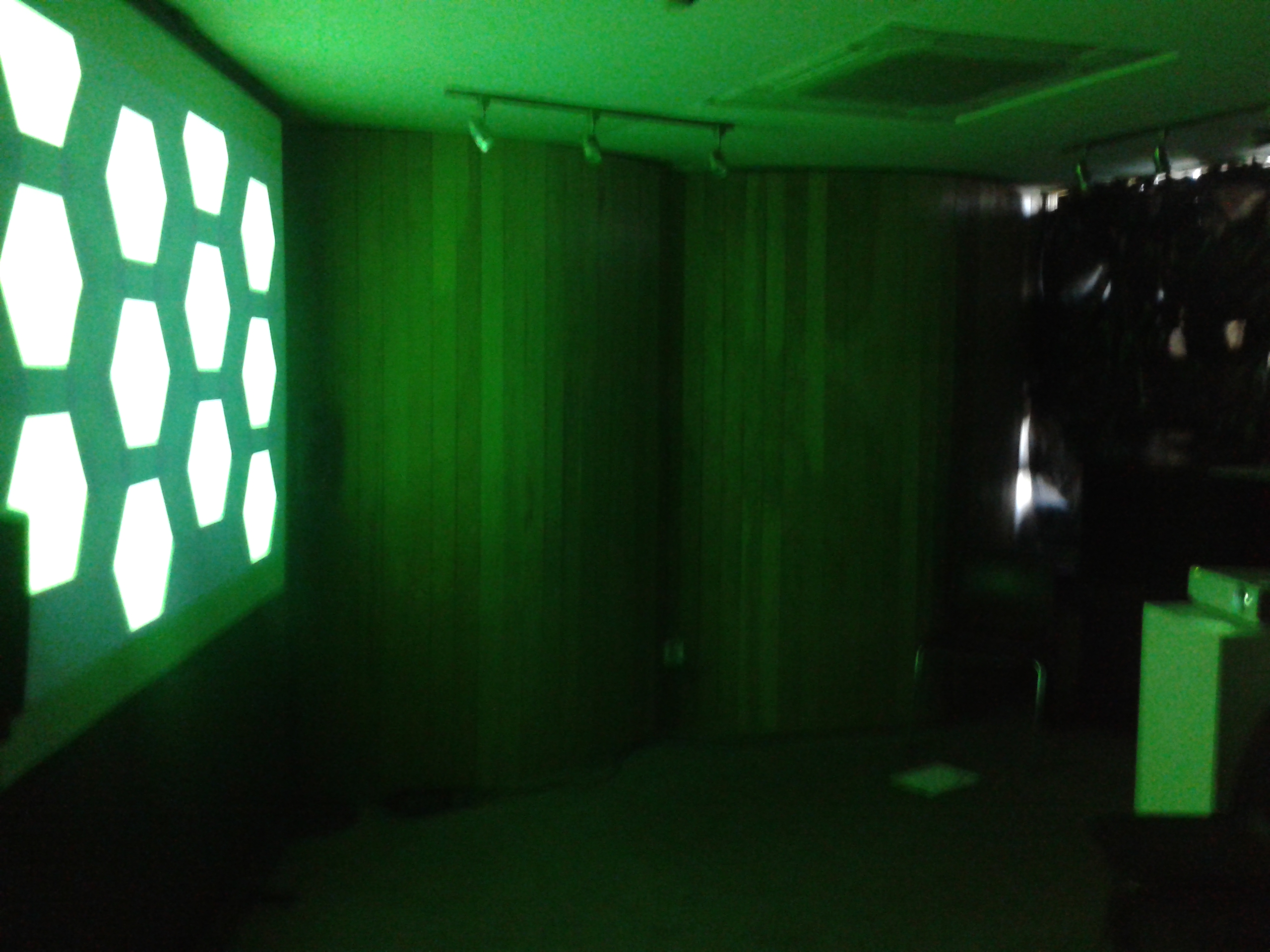
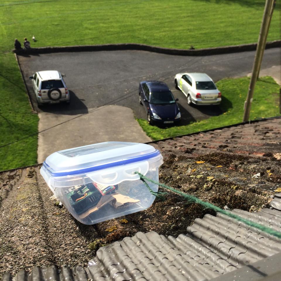
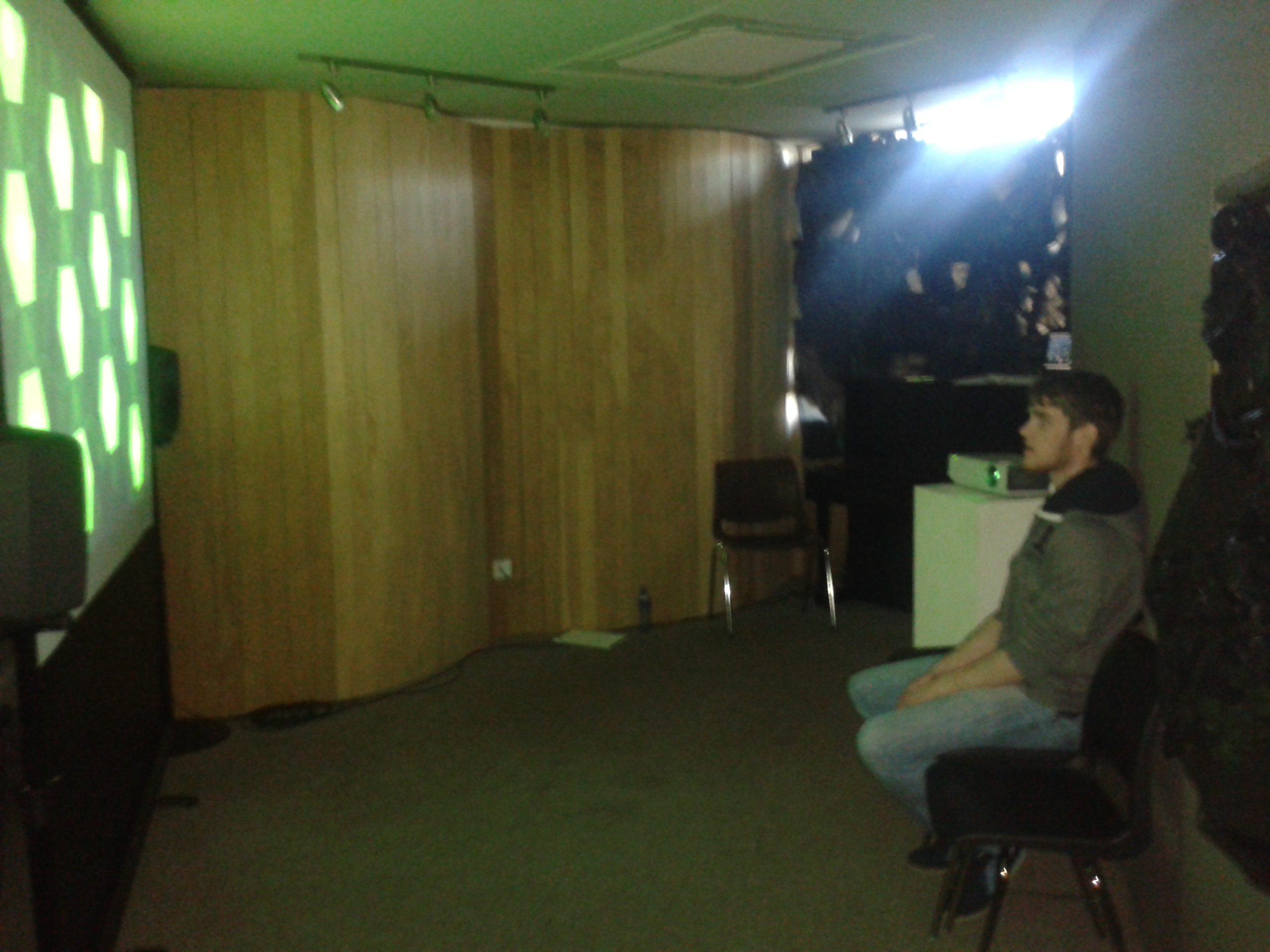
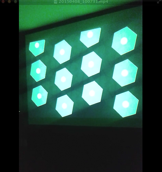
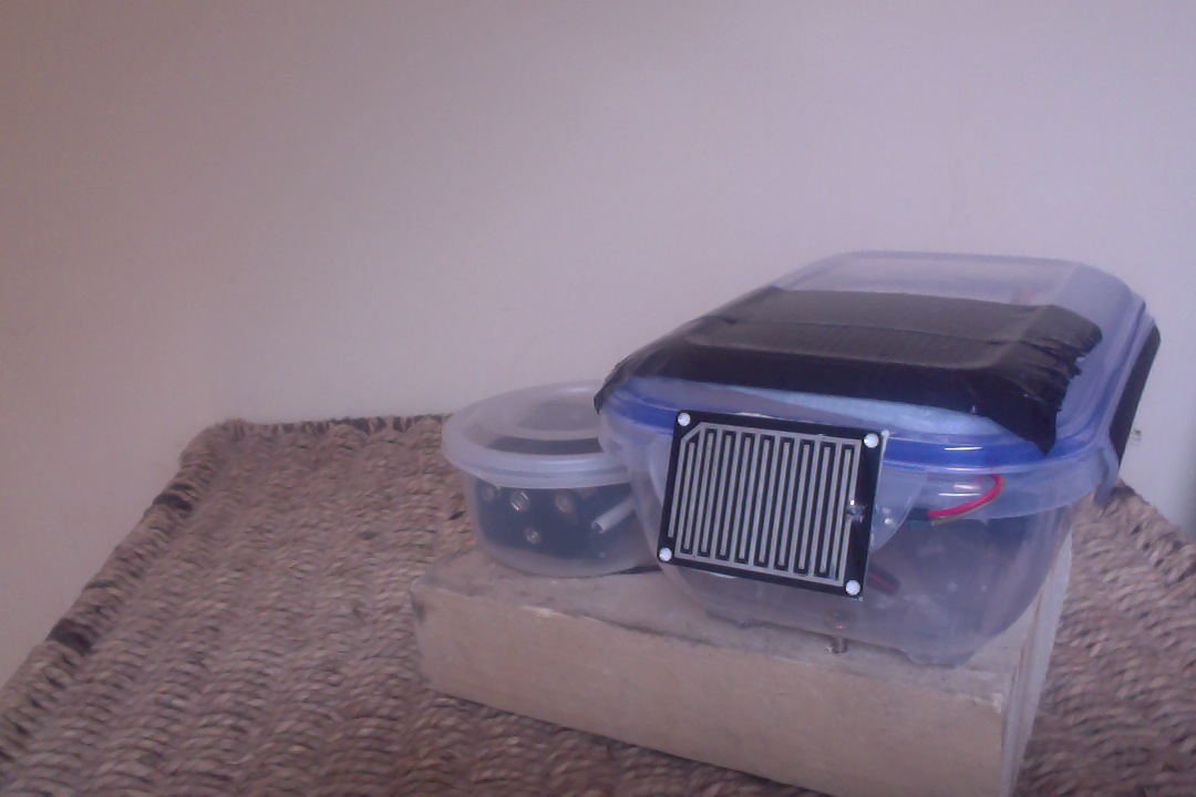
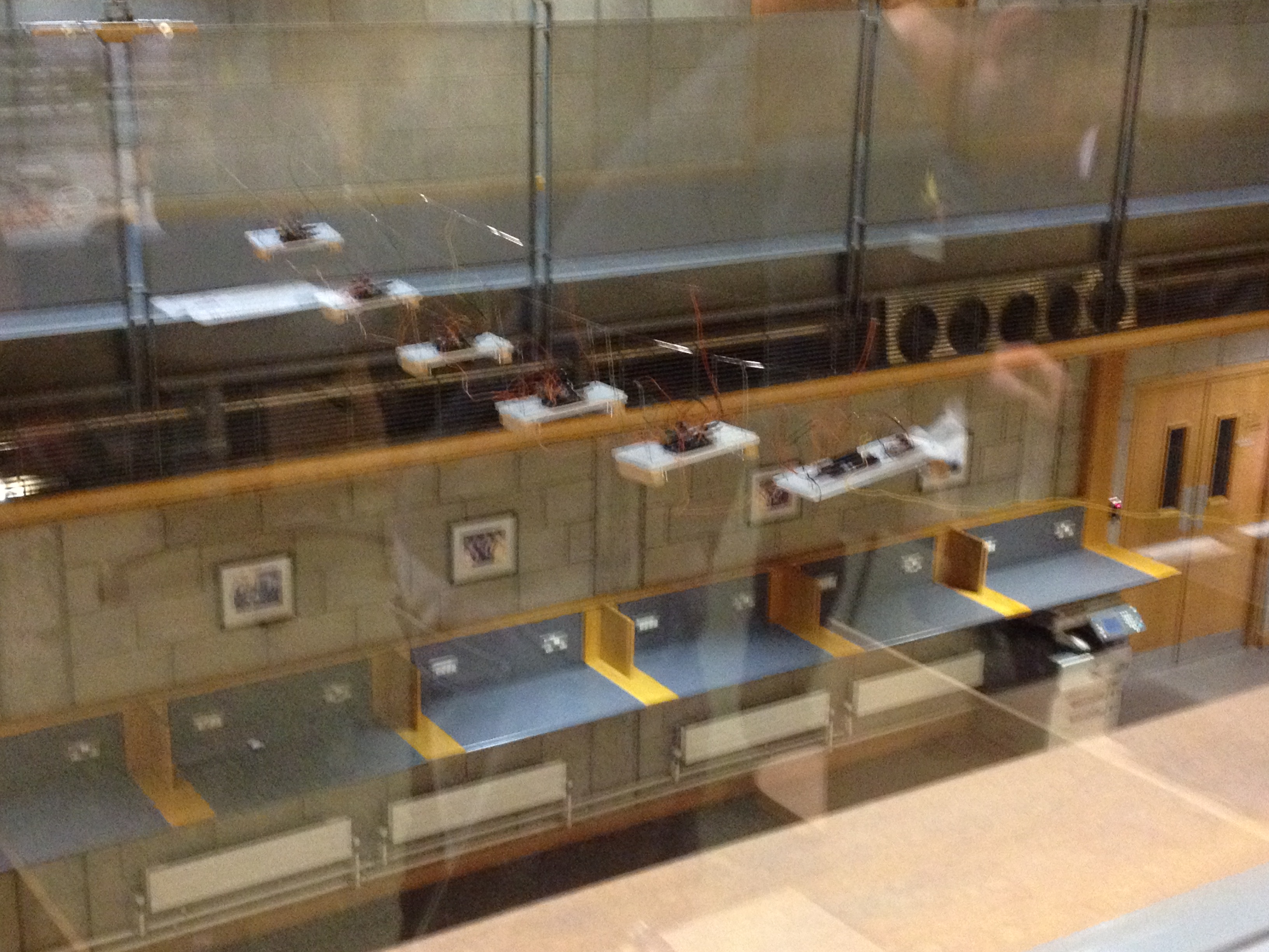
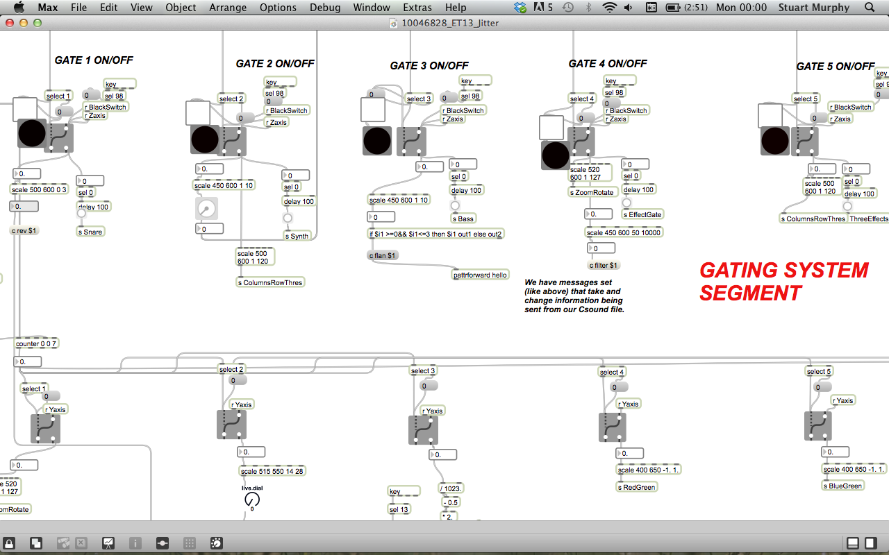
To assist the extensive research regarding aesthetics and utility, an ambient weather display was created that could transmit information in the background or the periphery of a person’s attention, whereby a person could check the state of a display by glancing at it and not be overwhelmed with information processing. This ambient display used both audio and visual communication channels to inform observers of the current weather conditions based on where the weather station was located. A mini weather station was designed and placed outside the Computer Science building in UL whereby its meteorological sensors acted as inputs to generate a dynamic soundscape and visualization in real time indoors. Through data analysis, normalising data and mapping techniques, the output of data was more than arbitrary. The colours, speed of movement, positioning of shapes, key, scale etc. created changed to reflect updates in the data thus becoming a narrative. The metaphorical data output prompted a link with the human minds understanding of the world relating to weather via the aesthetic contextual undertones that may worry, annoy, relax, and excite a person.
Software used
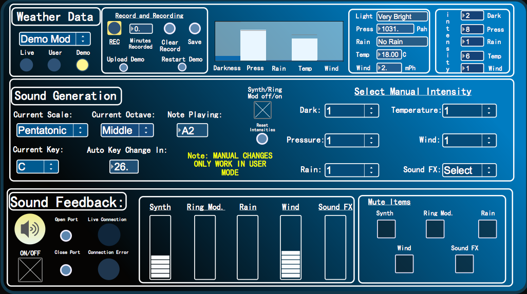
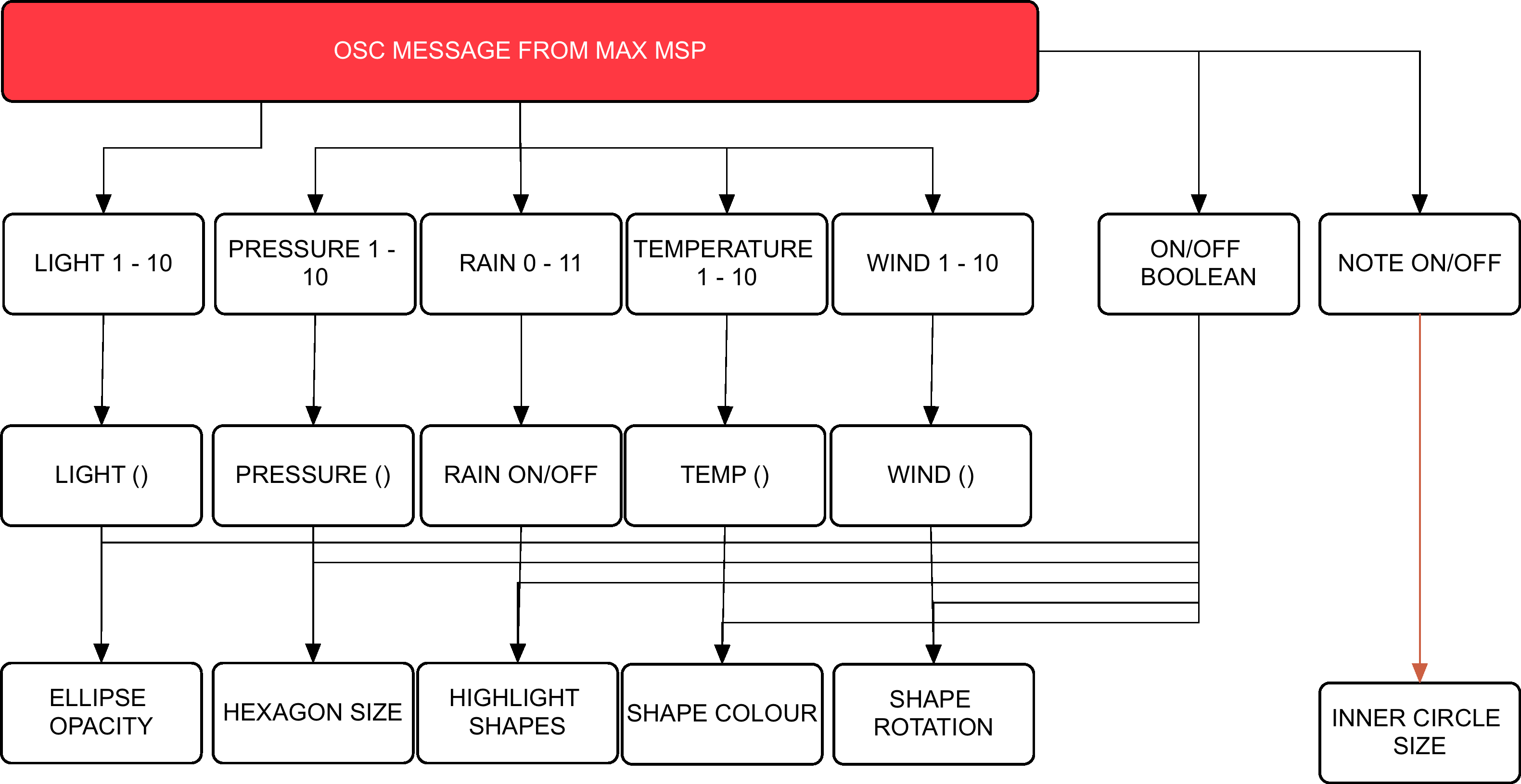
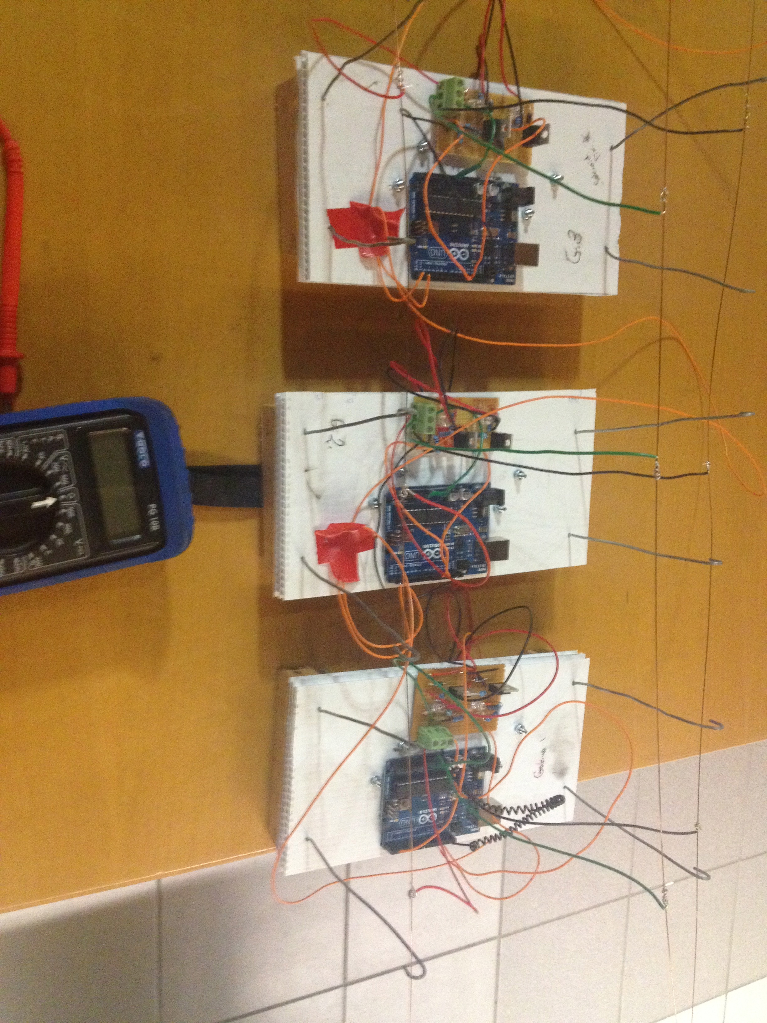
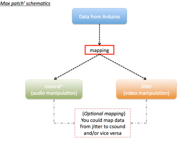
Arduino controls the meteorological sensors that monitor weather behaviour. This data is then sent to Max MSP via the Bluetooth module. Max MSP is responsible for calculating the weathers ‘pleasantness’, generating the audio attributes of the project and then passing the intensity levels onto Processing in a form of OSC messages. Processing then generates the visuals on screen whereby the dynamics will synch with the audio output.
Hardware
Arduino Uno, Barometric/Temperature Sensor, Rain Sensor, Wind Sensor, Photocell, Bluetooth Module, 6 AA NiMh batteries.
Microcontroller & Power Supply:
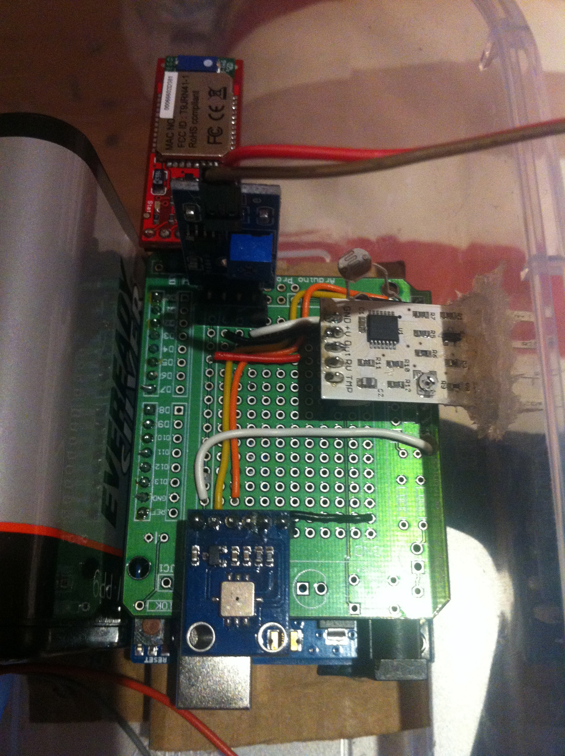
The type of microcontroller that was chosen for this project was the Arduino Uno R3. This is a microcontroller on a circuit board, which makes it easy to receive inputs and drive outputs. The Arduino Uno can be used to develop stand-alone interactive objects or can be connected to deliver data to software on your computer (e.g. Processing, Max MSP). Programming can be uploaded to the board to dictate its performance. The board provides the project with what is needed to incorporate several sensors, send data and also allow external power source. Through testing various power supplies (9v pp3, 9v pp9 and a pack 4 Alkaline 1.2v batteries all failing requirements) the best alternative to bring power to the circuit was a pack of 6 NiMH rechargeable batteries that had a capacitance of 2000 mAh each.
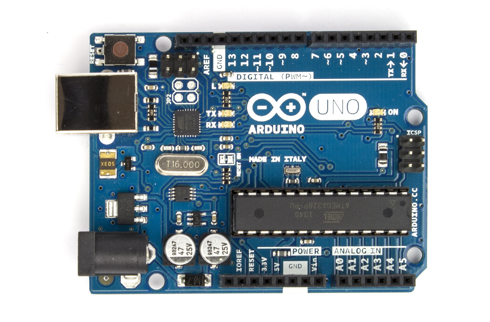
Arduino Uno
Photocell
The goal with being able to monitor the amount of light was an attempt to deduce the amount of cloud coverage. If there was more overcast as a result of blocked sunshine, then light levels would reduce. Light levels of a specific area could be assessed using a basic miniature Photocell. Photocells are capable of reacting to ambient light. Experimentations were considered with various resistors to accompany the photocell on the circuit but ultimately the Arduino’s internal resistor, 20k resistor, was called into use via the sketch. Any subtle changes in light values were to be monitored using specific ‘if statement’ objects within Max MSP.
BMP085
Air pressure and temperature are two key features when determining weather state. Low barometric pressure and temperature signifies ‘unpleasant’ weather whereby high-pressure readings and high temperatures normally result in ‘pleasurable’ weather. Fortunately there is a sensor that can monitor both, the BMP085. Precaution has to be taken when mounting this sensor. Its data sheet indicates that it must be well ventilated, advice that needs to be deliberated considering the weather station will be situated outside and exposed to hot air being trapped within the enclosure, resulting in inaccurate readings. The sensor itself is also sensitive to light. It can influence the accuracy of the measurement of the photocurrent silicon.

BMP085
Wind Sensor
Cautious installation had to be implemented for the final two meteorological sensors; wind and rain. This is because these two need to be exposed to the outside of the enclosure, with non-waterproof parts remaining protected from the elements. The way that the wind sensor is constructed allows the tips of the sensor to be exposed through a slot or detached from the main body and extended. The sensor uses a traditional sense of measuring wind speeds. It uses what is called a “hot-wire” technique. A constant temperature of an element is maintained. The wind changes will then vary the temperature of that element and it is the measurement of the amount of electrical power needed to maintain the constant.

wind sensor
Rain Sensor
The rain sensor is equipped with a board to be exposed to the rain and a control board, which will be integrated into the circuit within the enclosure. The basic explanation of how this sensor works is that it is an alternative variable resistor. The rain board that sits outside the enclosure will determine how much current will follow through it based on the wetness of it. The wetter the board, the more current is conducted. The project circuitry uses an analogue pin to receive signal in oppose to using the digital ones. This way can determine just how wet the board is ranging 0 – 1023.

rain sensor
Wireless Communication
For a project of this magnitude, using Bluetooth as a means of communicating data seemed appropriate. This means that distance between station and a paired computer point is limited to 10 meters at best but, given the correct location, would function perfectly. The BlueSMiRF Gold was selected as the most suitable for sending the weather stations data. It is capable of doing so by establishing a connection with the paired computer’s Bluetooth serial port and performing serial communication.

Bluetooth Module